イオン源 |
Beam Profile Measurements IonEtch Sputter Gun
|
|
The beam profile measurements were made with a IonEtch Sputter Gun with standard ionoptics having a 1.5mm aperture. As detector a Faraday cup having a 2mm2 Aperture. The Faraday cup was mounted on a precision manipulatorat a distance of 100mm. To avoid an influence of electrons when measuring the ioncurrent the Faraday cup was biased.
Parameters:
・UA: Anode Voltage (positiv)
・UE: Extractor Voltage (negativ)
・Ug: Bias Voltage to repel electrons (negativ)
・pK: chamber pressure.
・PMW: input power to the magnetron.(mA)
|
| |
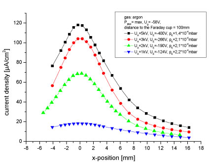 |
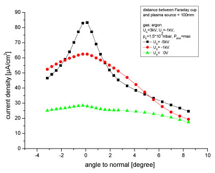
| Figure 1: measurement of the beam desity at different anode voltages. The chamber pressure and the extractorvoltage were set such that a high current is reached at X=0 position. |
| |
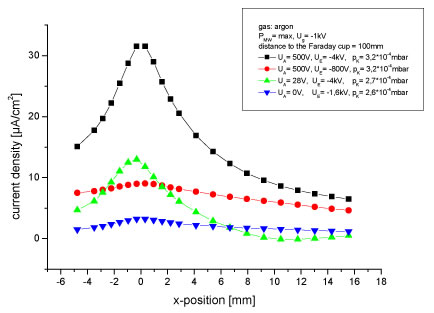 |
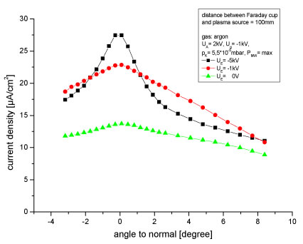
Figure 2: current density at low anode voltages. The Faraday cup was biased to repel the electrons.
Remarks to the measurements at low ion energies:
The bias voltage is needed to repel the electrons from the Faraday cup. At high extractorvoltages (UA) it had been observed that the measurements have been influenced by theelectrons. For that reason the voltage was increased to 1kV to repel at least most of theelectrons.Unfortunately this also influences the measurewment of the ion current as the effective area ofthe Faraday cup is increased. In fig. 2 no change is expected at UA = 500V but at UA = 28V anincreased value at a factor of 2 to 2,5 is expected (the factor has been determined from a simulation). |
| |
 |
| |
 |
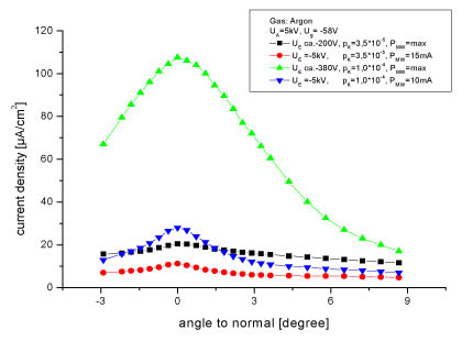
| Figure 3: angle distributiom for different extractor voltages and base pressures. |
| |
 |
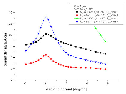
| Figure 4: angle distribution for different extractor voltage. |
| |
 |
| Figure 5: angle distribution for different extractor voltages |